IP-Radios - The New Studio-Transmitter Link (STL) | Telos Alliance
By The Telos Alliance Team on May 4, 2016 11:56:18 AM
IP-Radios - The New Studio-Transmitter Link (STL)
Abstract
Radio broadcasters have traditionally used 950MHz analog or digital point-to-point radio systems to transport their audio programming from the studio to the transmitter site. Leased T1 or E1 digital land-based circuits have also been popular where a line-of-sight radio path cannot be established. Each system has strengths and shortcomings; the radio STL is one-way only and has little room for ancillary data. The landline T1/E1 solution implies a monthly lease expense, as well as high capital costs for the endpoint equipment, and still not much extra data bandwidth once the program audio is transported. With multi-station shared transmitter sites, HD Radio, off-site automation backup, security cameras, remote control, and Internet access all becoming necessities, a reliable, high-bandwidth data transport scheme becomes critical. Enter the modern 2-way IP-radio system. These carrier-grade links can transport several stereo audio channels with bit-for-bit clarity, plus provide for all the other data services just mentioned and have room for growth. This paper describes not only the STL needs and challenges facing broadcast engineers, but provides clear, workable solutions both in the abstract and specific solution cases.
Traditional STL Systems
 Studio-Transmitter Links (STLs) have for decades been analog RF transmitters and receivers, typically in the 950 MHz band (in the USA). Some systems were monaural, others consisted of 2 monaural transmitters and receivers, each pair being offset in frequency from the center of an STL channel to provide a stereo path. Many systems were and still are “composite” STL systems where the stereo multiplex signal is generated at the studio and passed faithfully to the FM transmitter over a Composite STL radio system. In all of these systems, some relatively slow-speed data
  could be sent from studio to transmitter site using subcarriers. The mid-1990’s saw the introduction of digital STL systems. In these, analog or AES audio input was bit-rate-reduced using MPEG 1 Layer 2, MP3, or aptX® algorithms and transmitted as a serial bit stream to the receiver for decoding. Later, linear audio digital STL systems became available. Still, these are one-way (simplex) studio-transmitter links with no return audio or data path. Moreover, there still isn’t much data rate available, even in these digital STLs.
More Data Bandwidth, Please
Broadcasters are seeking more bandwidth - specifically, Internet Protocol (IP) bandwidth - between studio and transmitter. Commercial Internet service is often not available at remote transmitter sites, so engineers are looking to provide their own solutions where needed. Today, a variety of appliances and services are remotely usable with an IP connection. Security cameras, off-site file servers, VoIP telephone, and, of course, a high quality IP-based Studio-Transmitter Link highlight the need for reliable IP connectivity that is 100 percent under the broadcaster’s control.
IP Works - But Reliably?
IP connectivity between two points can take several forms. If commercial Internet service is available at both endpoints, then simply paying a monthly fee for it can be a good way to connect. In most cases, however, broadcasters desire more reliability than we often find is actually provided by typical ISPs.
Broadcast engineers would like to see “Five 9s of reliability” or better. Five 9s equals 99.999% uptimes. This translates to downtime of 5 minutes and 15 seconds per year. Six 9s (99.9999%) uptime is even better, implying only 32 seconds of downtime per year.
Experience shows that many ISPs typically deliver only three or four 9’s of reliability. That level equates to between one and nine hours per year of downtime. Sadly, it’s not uncommon to experience two 9’s (99%) of uptime, equating to about 3½ days of downtime each year. Experience varies widely with commercial ISPs, with some broadcasters suffering through daily or weekly outages (worse than two 9s), while others are getting that five 9s reliability.
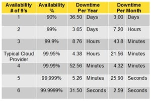 For use as an audio STL poor reliability with frequent outages is wholly unacceptable to broadcasters. Either a five or six 9s IP link is needed, or a main and backup IP connection for both ends is required.
Commercial Internet service linking two sites is likely worse when there are two different ISPs involved. With just a single ISP, there’s a good chance that site-to-site data is routed the shortest possible way, and will likely stay within the same city or region as the two endpoints. If it’s necessary to use two different ISPs, there’s a very good chance that all the point-to-point data will be routed out of the area to a “gateway” location. This is a data center where several ISPs and backbone providers interconnect with each other. If one endpoint is on Verizon, for example, and the other is on CenturyLink, then all the data traveling between the two may be routed halfway across the country in order to interconnect. Staying within the same ISP from end to end will very likely result in the highest reliability for commercial Internet service.
IP Radios
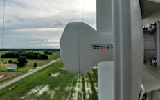
If a line-of-sight path is available between studio and transmitter sites, or even via an intermediary “hop” point, the option opens to consider installing IP radios. IP radios can provide a very reliable (five or six 9s of uptime) IP connection. Moreover, modern IP radios convey IP packets with bandwidths approaching 1 gigabit per second, though more typical bandwidths may be 50 to 100 megabits per second. Whatever bandwidth the IP radios will support over a given path, this option is likely to be very reliable and shouldn’t involve any recurring monthly costs.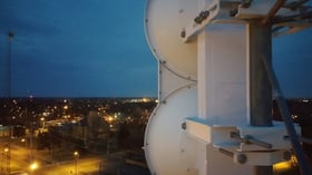
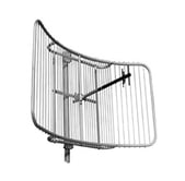
IP radio antenna systems vary among models, too. While “flat panel” antennas are popular for general Internet access from Wireless Internet Service Providers (WISPs), they cannot provide the extra gain margin and off-axis interference rejection of a parabolic antenna.
Some IP radio models feature a “split” electronics package, with the bulk of the circuitry in an indoor- mounted unit. Then, the up/down converters, pre-amp, and output amp in an outdoor unit, typically mounted on the back of the antenna. Many IP radio models - especially the crop of less-expensive one becoming popular - feature an all-in-one design, with the electronics package part-and-parcel with the antenna(s). Still others offer a mix-and-match topology where a small, outdoor electronics pack can be coupled to large, medium, or small antennas.
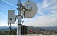 One additional differentiator in IP radio systems is whether they are half-duplex or full-duplex. Half-duplex systems cannot actually transmit and receive simultaneously. Rather, they switch between transmit and receive at a rate that is optimal for the path length, providing the most efficient throughput possible in half-duplex scenario. Full-duplex systems don’t have to alternate transmit and receive; they can transmit and receive simultaneously full-time. This allows not only better throughput but affords less jitter in the IP packets delivered to each far-end network. For ordinary IP transport, half-duplex works fine. However, for time-critical Audio over IP (AoIP) applications, full-duplex offers some benefits to reliable operation. An excellent explanation and visualization of simplex, half- and full-duplex systems is presented here.
Licensed and Unlicensed
IP radios are available in a variety of sizes, frequency bands, power levels, and feature sets. They’re also available in licensed bands, requiring frequency coordination and regulatory licensing, as well as unlicensed bands. Unlicensed IP radio systems may be quick and easy to purchase and install, but may be subject to interference from other users on the same or adjacent frequencies.
Whether a point to point wireless link is designed and deployed in either licensed microwave or unlicensed frequencies, the expense for equipment and the time it takes to deploy the equipment is the same. The only practical cost difference is the licensing fee.
Licensed RF transmitters communicate using a specific transmit and receive frequency combination that is selected and assigned to the user (licensee). Licensed microwave wireless systems operate within parts of the radio spectrum, such as: UHF/VHF, 900MHz, 2GHz, 3.65GHz (WiMax), 4.9GHz (public safety), 6GHz, 11GHz, 18GHz, 23GHz, and 80GHz (E-Band millimeter wave) as designated by the FCC.
Licensed microwave wireless systems are becoming more popular as a result of noise interference in unlicensed wireless spectrum, most notably in built-up urban areas. Licensed microwave radios provide good security from the risk of interference from other RF systems. In a licensed system the channels that the radio system transmits and receives on are allocated to the user and are registered with the FCC after frequency coordination. Getting a license is reasonably inexpensive and can be obtained in the matter of weeks.
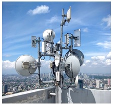 Prior to deploying and operating a licensed frequency an end user is responsible for performing a frequency coordination, filing a public notice, and submitting an application (FCC Form 601) with the FCC to ensure that no one else is already operating on the same frequency or a frequency that will inject interference on existing systems. This process provides full disclosure of the frequency assignment and typically avoids interference from any existing licensee already assigned in the area. If licensed radios encounter interference, it is typically resolved with the assistance of the FCC or other regulatory body.
With unlicensed systems there is no guarantee that a system will operate interference free. However, many unlicensed systems can overcome interference by having a good carrier to interference ratio inherent with the hardware and by proper design and installation. Indeed, the high-gain parabolic reflectors (antennas) used in point-to-point microwave systems typically provide excellent rejection of undesired interfering signals.
The major difference between licensed wireless and license-exempt systems, then, is that licensed radio users have a regulatory body that will assist them in overcoming any interference issues that may arise, while license-exempt users must resolve interference issues without governmental assistance.
Getting IP from Here to There (and back)
One of the first steps in considering an IP-radio approach to STL is a path analysis. It must be clear that a line-of-sight path exists between the endpoints, along with adequate clearance for the Fresnel Zone. (Information about Fresnel Zones and their importance in radio communications is found in this Wikipedia article.) Modern online mapping tools actually turn this task into a fun exercise. One such path analysis tool is provided by IP radio manufacturer, Ubiquiti at https://airlink.ubnt.com. This online tool incorporates Google Maps, including road, satellite, and terrain views. A map layer showing Terminal Doppler Weather Radar locations and frequencies
is also available, as these operate around 5.6 GHz. Frequency separation must be considered when planning a 5 GHz IP radio link near these TDWR installations.
Using Ubiquiti’s “Outdoor Wireless Link Calculator” is a convenient and free approach to analyzing a proposed microwave radio link.
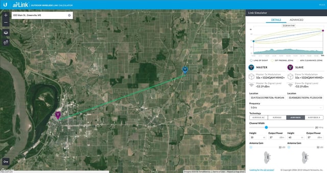
- Locate and place the “Master” (blue) drop pin at the beginning endpoint - usually the studio.
- Locate and place the “Slave” (red) drop pin at the ending endpoint - usually the transmitter site.
- If your path is more than 5 kilometers or so, you’ll end up zooming and panning around the map to locate your endpoints. You may also use the address search function to get close to your desired sites. If the default road map view doesn’t show enough detail to find a site, turn on the satellite view. In most cases you’ll find an aerial view of even remote transmitter sites. Place your endpoint pins carefully, as the Height Above Mean Sea Level (HAMSL) will be interpolated from your pin placement and used for the path clearance calculations and diagram.

- In the Link Simulator sidebar, select your desired frequency band from the dropdown list. 5 GHz is a good place to start. If your path is short and you don’t feel that rain attenuation will pose a problem, then consider 24 GHz.
- Also in the Link Simulator sidebar, enter the height in meters that your antennas will be placed above ground level.
- If the path line on the map is green, you’re probably in good shape for both line-of-sight and Fresnel Zone clearance of your IP radio link. A yellow line indicates partial Fresnel Zone clearance of at least 60%. A red line indicates not even line-of-sight clearance is available at the proposed locations and heights. Adjust the heights at the endpoints to understand the feasibility of your proposed link. Keep in mind that the elevations shown across the path do not include building and trees. The user will need to include those factors and any other obstructions in a final path determination.
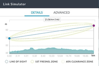
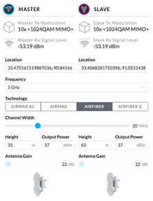
- The Link Simulator on Ubiquiti’s web site includes options to select different IP radio models and antenna sizes. Modulated channel width is also selectable. Bear in mind that while wider RF bandwidths afford more data throughput and fancier modulation schemes, the do so at the cost of more susceptibility to interference and requiring a higher received signal strength. Higher reliability across the link is gained by reasonable RF bandwidths and less complex modulation modes. For reliable STL service, a broadcaster is likely more interested in more robust operation with no packet loss or error corrections required, while sacrificing top-end data bandwidth to achieve best reliability.
The Next Considerations
Once a determination is made regarding microwave path viability, and the elevations required at each end for live of sight (LoS) and Fresnel Zone Clearance, it’s time to think about the other parameters of an IP radio system.
- Licensed vs. Unlicensed
- Frequency band (varies by political boundary)
- Antenna mounting
- Lightning protection
- Weather-resistant installation materials
- Coax or CAT5e outdoor-rated cable
- Outdoor-rated cable attachments
- Antenna grounding
- Cable grounding
- Cable surge suppression devices
The intended use-type of the IP-radio system also needs consideration as it affects the performance required. One may divide the performance requirements into two IP-audio use scenarios:
- Near Perfect (for Livewire and other clocked AoIP transport): Expect to transport low-latency, clocked, networked audio, such as found in AES67, Livewire+®, Ravenna, or other popular professional audio networks. This use case demands very low jitter and no packet loss across the IP radio link. Consider that the IP radio link must be nearly indistinguishable from a length of CAT5e cable in terms of data throughput and packet handling performance. Several benefits accrue from employing this IP connection scenario.
- Lower audio latency from end to end
- AoIP network as the near-end equipment.
- Lower AoIP audio equipment cost. It’s often the case that only an audio “Node” is required at the far end. These are typically much less expensive than IP-audio codecs, and operate the same way they would on the near-end AoIP LAN.
The key downside to this IP connection scenario is that excellent - indeed, near perfect - operation required from the IP radios. Data error correction schemes are disabled as using them requires extra time that may not be available in a low-latency AoIP scenario.
- Less than Near Perfect (for unclocked AoIP and general IP traffic, including coded audio stream): Expect to transport coded audio streams, or linear RTP streams, such as available from several manufacturers’ IP codecs. Coding may be in any popular algorithm such as MPEG Layer 2, MP3, aptX®, or AAC - whatever is offered by the chosen IP audio codecs. Linear (non-bitrate-reduced) audio may also be sent using codecs or Nodes offering Unicast RTP communication. In these IP-audio modes, there is no guaranteed clock sync between the two ends of the path, so very occasionally and audio click or dropout may be produced. These may be every few hours or every few days, so it’s generally not considered problematic. The benefits of employing this more relaxed IP connection scenario are as follows:
- Less critical IP radio configuration. Some models may work nearly “out of the box” with little tweaking.
- Error correction offered by the IP radios may be used.
- Longer path lengths and less robust modulation schemes may be used.
The downsides of this use case will be higher audio latency, higher expense for purchase of dedicated IP-audio codecs, and perhaps lower audio quality as bitrate-reduction will take a slight toll on audio quality.
Real-World Results
Rural Path - Cheap IP Radios
Under conditions involving a clear microwave RF path, it has been shown that even very inexpensive IP radios can handle the “Near Perfect” requirements for that operating scenario. In the “What’s Working” section below you’ll see the path clearance and the IP radio configuration that is working for two Livewire Standard Streams in each direction over a six-mile path. It has also been tested with 4 Livewire Standard Streams in each direction and found to work fine as well.
The IP radios used 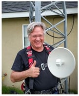 - Ubiquiti NB-5G22 NanoBridge M5 - were purchased for under $100 USD each. Indeed the high-quality outdoor- rated, shielded CAT5e cable, shielded connectors, and CAT5e surge suppressors cost nearly as much as the IP radios did. The IP radios were so inexpensive that an additional pair was purchased for off-the-shelf backup.
These inexpensive IP radios are carrying two Axia Livewire Standard Streams in each direction. At the far end (transmitter site) only an Axia xNode is there to convert the linear audio Program streams into analog audio for two stations’ audio processors.
Interference to the 5 GHz IP radio link is not anticipated as the RF path is entirely over flat farmland, with nearly zero population. A test with the Ubiquiti’s built-in site-survey analyzer showed absolutely no other RF in the 5 GHz unlicensed band.
Small Town Path - Full-Duplex IP Radios
In another real-world case, reliable STL for four FM radio stations is needed from a studio in a small town of 35,000 to a new transmitter site, common to all four stations. The IP radio RF path crosses the downtown area, proceeds across a university’s agricultural experimentation complex, and looks directly through a multi-carrier cell tower close to the far end (transmitter site). The RF path is just over 13 miles long, and can be viewed in the “What’s Working” section below.
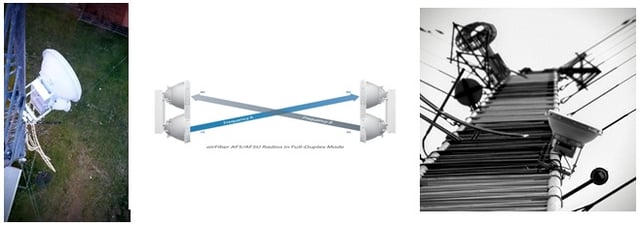
For this STL system, a full-duplex IP radio system was chosen - the Ubiquiti airFiber 5. To achieve full- duplex operation, this IP radio system has 2 antennas at each endpoint - one for full-time transmit and one for full-time receive. This scheme reduces the effective jitter from packet to packet, making the IP radio system behave more like a long run of Ethernet cable.
These much larger IP radio systems cost about $1,000 each. Add the long runs of outdoor-rated, shielded CAT5e cable, outdoor cable attachments, grounding, plus CAT5e surge suppressors, and the total IP radio cost was just under $3,000.
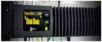 An Axia AoIP system already exists at the studio, serving all 4 FM stations. As such, only 1 additional Axia xNode was needed for the transmitter site. This xNode brought the entire cost for a 4-station linear STL system to about $4,600, or under $1,200 per radio station.
The IP radio system is carrying other IP data between studio and transmitter. Some additional Cisco switch configuration allows for additional IP access without causing any dropouts of audio. In other words, the IP-audio packets always have priority and bandwidth to traverse the link first. Other data is be rate-limited, if necessary. The transmitter site is outfitted with interior and exterior security cameras, an automatic weather station, and a VoIP telephone. A backup of all stations’ automation audio can be updated over the link. Plus, other IP devices will be connected and remotely controlled in the future.
Highest Quality - Carrier Class IP Radios
Many broadcasters want to use the very best IP radio systems. Manufacturers in several price ranges may call their radios “Carrier Class”, but long-time installers, users, and consultants point out that the real Carrier Class IP radios are those that are built from weatherproof metal chassis and exhibit superior protection from lightning, wind, soaking rain, hail, and other hazards. Carrier Class IP radios tend to provide a high degree of “peace of mind” for the user, and this reputation is typically well-deserved.
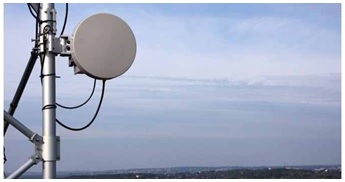 These IP radios not only look rugged, they usually perform as “good” - and as ruggedly - as they look. They are available in both licensed and unlicensed bands, though users of this level of IP radio will typically obtain licenses to protect their investment. Not only are the materials of superior quality, the design care of the mounts, antennas, and radio packs are quite robust.
Some Carrier Class radio systems will have most of the electronics - especially the IP network electronics - “on the ground” in an indoor unit. Instead of an Ethernet cable carrying data and power to the antenna and its microwave electronics, you’ll often find a coax cable carrying power and an Intermediate Frequency (“IF”) signal from the indoor electronics up to the antenna.
Older Carrier Class microwave systems were originally offered with interfaces common in telephony service. T1 and E1 interfaces w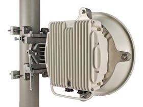 ere common on these systems until recently.
With the popularity of IP connections, manufacturers began offering these in addition or instead of the channelized telco connections. Moreover, older microwave radio systems were designed for robust and reliable operation, favoring that over raw speed of the data throughput.
Nowadays, these Carrier Class systems can offer all the features of their cheaper, upstart brethren. The cost is still quite a bit more, but you can see the difference in quality and assume a longer service life - perhaps much longer.
System Configuration
The chief goal of proper IP radio system configuration, is to obtain reliable data transfer from end to end. For the more stringent case of “Near Perfect” data transfer, we have the additional goals of zero packet loss and low packet jitter; in other words, we also want the IP radio link to operate very much like a wired connection would.
It may be possible to fully (or nearly so) configure an IP radio link on the ground. Very likely the on- the-ground operational results will be worse than after proper installation as part of a working path. Indeed, it’s possible that your IP radio link won’t work properly at all in a confined space such as an office, hallway, or even in a back yard. You’ll find that antenna placement with regard to walls, floors, ceilings, and other objects is critical and affects the IP radio operation significantly.
We noted that the small Ubiquiti NanoBridge M5 could be made to work in an office test with careful placement of the antennas. The larger Ubiquiti airFiber5 would not connect at all in a closed environment, and would not work properly in a backyard environment, either. The best practice, then, is to configure everything about the IP radios required for wired IP communication with each one while on the ground. Further configuration - that which affects packet reliability and other fine-tuning parameters - may have to wait until the IP radios are installed and aimed at each other.
Some initial configuration requirements are considered “baseline”, and must be properly in place before more detailed configuration can be done. These basic requirements include the following:
- Pre-mounting configuration will likely involve just enough setup to ensure the radios can receive each other, once mounted above ground.
- Set the networking parameters for communication with the IP radios. Depending on your network configuration, it will likely make sense to use IP addresses for the near and far IP radios that fit in with your network’s addressing scheme. Static IP addressing is highly recommended. Many IP radios offer NTP time synchronization for keeping their log date and time accurate. Some also offer SNMP monitoring, Telnet, https, and even Dynamic DNS updating. These services may require Internet access through a router.
- If the IP radios are to be part of an existing clocked AoIP network, such as Livewire, AES67, or similar, use informed caution when connecting this kind of network to other networking devices, such as routers. Many consumer-grade devices, and even commercial-grade devices will impede AoIP network operation if not properly configured.
- Set the band, frequency, and channel width that are expected to be appropriate for this installation.
- In the unlicensed bands, users have freedom to use any frequency within that band. Some IP radios include a spectrum analyzer to observe signals from other sources coming into the IP radios’ receivers.
- Choose a part of the desired band that shows the least energy from interfering sources. Remember, these IP radios use spread spectrum technology, so interference is less likely than with analog radio systems.
- Tight beamwidths from good antennas also reject most off-axis energy. Good operation is very likely even with some interfering signals, especially as both ends’ antennas will be aimed directly at each other. This maximizes the desired-to-undesired signal ratio.
- Half-duplex systems have one frequency setting for each end, and it will be the same for each.
- Full-duplex systems will have separate send and receive frequencies. These will be transposed on one end compared to the other.
- Mount the IP radios and antennas at the heights determined by a path analysis.

- Antenna mounting involves several mechanical considerations, including attention to additional tower loading.
- The antenna manufacturer’s instructions regarding grounding and weatherproofing should be observed.
- Proper installation of shielded RJ45 connectors is critical to provide a ground path for the protective foil shield and drain wire.
- CAT5e-compliant surge suppressors should be installed at both ends of each CAT5e cable run.
- IP radios requiring power (electronics located on or near the antenna) are typically powered through the Ethernet data cable via a connection called “Power over Ethernet” or “PoE”. Several standards exist for PoE. The most common one, supplying 48 VDC, over unused pairs in 100BaseT
- IP radios & antennas aimed toward each other, both in azimuth (left / right) and in elevation (up / down).
- Microwave antennas and their mounting hardware typically will have adjustments for “fine tuning” of both azimuth and elevation.
- Initial aiming may be done with visual reference to objects in or near the RF path.
- Final aiming is done referencing the received signal strength from the far-end antenna.
- To use signal-level aiming on one antenna, the other antenna needs to be aimed well enough to be providing some usable signal level to the one being aimed. Note that all antennas - including parabolic reflectors - exhibit “side lobes”. Swing each antenna enough to be sure the main lobe is aimed at the other antenna.
- Many IP radios have convenient signal-level displays built into either the active antenna feedhorn or the electronics on the back of the unit.
- Most IP radio antenna systems with an on-board signal meter will show the signal strength being received at that antenna. In this system (Ubiquiti NanoBridge M5) there are four LEDs on the side of the feedhorn cover. The calibration points of these LEDs may be changed to allow more or less granular signal level display if desired.
- Some IP radio systems can display not only the local received signal strength, but once a basic link is established it can display the far-end receive strength. This may allow more convenient final aiming for absolute best alignment.
- Signal strength is typically also offered on the web interfaces of IP radios.
- Once the receive signal strength is peaked and determined to be as-expected - or at least adequate - the antenna brackets can be locked down per the manufacturer’s directions.
- The IP radio link should now be providing at least basic HTTP communication between the endpoin This may be checked by pinging the IP address of the far-end IP radio, and further by pinging any equipment at the far end which you may have already placed on that network connection.
- Connecting the IP-audio network to - and through - the IP-radio link carrying Livewire (or other IGMP protocol)
- If the IP-radio link is extending an existing IP-audio network, the near-end IP radio will be connected to a port on an Ethernet switch. It’s likely that this port will be one on the “core” Ethernet switch for the IP-audio network.
- If there will be only one (1) IP-audio device at the far-end of the link, then the near-end IP radio may be connected to a switch port defined for “Access”.
- If there will be more than one IP-audio device at the far-end (e.g., two Axia xNodes or one xNode and one or more other Livewire devices) then the switch port must be configured as a “Trunk” port. Also, the qualified Ethernet switch at the far end must also be configured for a “Trunk” port, with this port connected to the far-end IP radio.
- These rules about “Access” and “Trunk” ports are the same whether the connection between a “core” switch is over a CAT5e cable or over an IP-radio link
- If the IP-radio link is extending an existing IP-audio network, the near-end IP radio will be connected to a port on an Ethernet switch. It’s likely that this port will be one on the “core” Ethernet switch for the IP-audio network.
- Configuration for Less than Near Perfect (for unclocked AoIP and general IP traffic, including coded audio stream)
- Many IP radio systems offer comprehensive automatic operation for the common use cases. If your IP traffic will consist of http, ftp, and other common protocols - especially those not requiring a “near perfect” connection, the IP radios may not require any further configuration. Follow the IP radios’ manufacturer’s directions for any further configuration to optimize IP traffic flow for your application.
- Check all the available configuration options to see if any services may be enabled to improve your experience over time. Services such as NTP, SNMP, Syslog, HTTPS, Ping watchdog, SSH server, and e-mail notifications may be offered. Consider which of these may be appropriate for your use.
- For example, if the IP radios offer an NTP client to set and keep their internal clocks accurate, and their network has Internet access, you may set these work properly. Here’s an example dialog:
- Unlike in case 3.d. Above, if there are no Livewire (or other IGMP devices) at the far end, there is no worry about using a “Trunk” port vs an “Access” port at either end of the IP radio link.
- Configuration for Near Perfect (for Livewire and other clocked AoIP transport)
- Many IP radio systems should be robust and accurate enough to transport Livewire and other clocked AoIP audio streams. A list of IP radio models which have been used successfully is shown at the end of this document in Appendix A. Note that equipment model designations come and go over time. Even brand names change as companies in this growing business sector are acquired, merged, or change hands.
Appendix A
IP Radio Equipment Models Known to Perform Adequately for Livewire.
Listed are Manufacturer and Model, notes about tested use and actual use, path length, and modulation scheme and bandwidth configuration. Other configurations may work as well, better, or more poorly.
In the early days of Livewire and initial IP radio installations, it appeared necessary to use “Carrier Class” (or “Carrier Grade”) IP radios. These systems are often used by telephone companies and other infrastructure entities requiring five 9’s of reliability, plus quick failover to backup systems. These Carrier Class IP radios were typically priced at $15,000 USD at the low end, and could easily go over $30,000 USD, depending on antenna sizes. Though the Carrier Class of IP radios are certainly still available and arguably provide the highest level of reliability, there is now a selection of economical IP radios on the market. Manufacturers such as MicroTik, Ubiquiti, Mimosa, and others are capable of the performance required for real-time, linear (and clocked) Audio over IP.
It’s worth noting again that most any IP radio system that is working properly is capable of transporting “coded” audio as produced by an IP audio codec. Examples of IP audio codecs would be a Telos Z/IP ONE or, for multiple audio channels, a Telos iPort PLUS. Such IP audio codecs may be set over a wide range of bits rates, depending on the bandwidth available and the audio quality desired. These Telos IP audio codecs may also be set to “linear” mode where the audio is not bit-rate-reduced, but may still be transported by typical IP radios. With reasonable packet buffering and using error-concealing codecs (AAC family) most any IP radio, properly working, will adequately carry this kind of audio stream. Remember that most IP radio systems will, by default, automatically adjust for a number of parameters and operating conditions. Such automatic adjustments will often result in some lost packets and perhaps brief periods of time when no data is crossing the IP radios’ path. For e-mail, file transfers, and web browsing, such brief periods of packet outages typically don’t present a problem. For continuous audio transmission, these periods may, indeed, cause brief loss of audio, even with buffering and error concealment.
For broadcast use, it’s recommended to more finely configure any IP radio pair. Such configuration is intended to eliminate automatic adjustments of operating parameters. Assuming a good, usable RF signal, the radios are set to operate constantly without the need for adjustment of parameters. Such parameters include power level, frequency, modulation mode (or scheme), and distance-based parameters such as wait-time for the next send cycle (in half-duplex IP radio systems).
Experience has shown that by setting most, if not all, “automatic” functions to a manual mode, and configuring that manual setting properly, IP radios will happily operate continuously and without trouble, as long as the RF path remains viable.
One non-intuitive parameter shown on some IP radios is the “Modulation Rate,” “Max TX Rate, Mbps,” or similar. This is referring to the modulation mode or scheme. It’s a label or code which references the data modulation scheme and maximum bit rate using that scheme in a given RF channel width. Explanation and a list of these codes and parameters is given here: https://en.wikipedia.org/wiki/IEEE_802.11n-2009
- Ubiquiti NanoBridge M5
- Tested with 4 Livewire Standard Streams, bi-directionally, over a 6-mile clear path. Used on-air for 2 Livewire Standard Streams, each with return Standard Streams for confidence audio.
- Following is the Basic Wireless Setting page for the studio-end IP radio. This end is configured to be an “Access Point” in the Wireless Mode. The far end is configured as a “Station”.
Note the Channel Width setting is 20 MHz, which seems to work best on this link. The Max TX Rate is set to “MCS 3 - 26” which indicates a modulation scheme of 16-QAM and a maximum channel bit rate of 26 Mbps.
- The “Advanced” configuration page exposes additional parameters that were important.
The “RTS Threshold” worked best at 200. The “Distance” setting worked much better when “Auto Adjust” is unchecked and the distance is entered manually. Best number to use is the actual path distance plus about 15 percent. “Multicast Enhancement” must not be Enabled.
- Ubiquiti airFiber5
- Tested with 4 Livewire Standard Streams, bi-directionally, over a 13-mile clear path. Used on-air for 4 Livewire Standard Streams, each with return Standard Streams streams for confidence audio.
- Here is the Basic Wireless Setting page for the studio-end IP radio.
We noted that the next higher Modulation Rate (16-QAM) setting worked fine as well. The goal is robust operation over sheer bandwidth, so QPSK is the setting for now. The link bandwidth is about 48 Mbps at the current setting.
- Note that the Ubiquiti airFiber5 IP radio has fewer configuration settings than the NanoBridge M5 shown above it in this Appendix section. The airFiber5 is full-duplex in its radio operation, implying that it has few or no parameters relating to radio timing for transmitter and receiving. It is transmitting and receiving simultaneously and constantly.
- DragonWave AirPair
- Tested 8 bi-directional Livewire Standard Streams over a 4-mile path. These DragonWave AirPair are in the 18 GHz licensed band. Seven Livewire Standard Streams are in-use 24/7 for 3 full-power FM stations, 3 translators, and 1 backup FM transmitter. These have been on since 2008, so long-term reliability has proven to be excellent. The 18 GHz band is affected by rain attenuation, and several outages of about 10 minutes have occured, each time during the onset of the heaviest rain in a thunderstorm.
- As the DragonWave AirPair is a highly professional, “Carrier Class” IP radio system, very little configuration was needed for this IP radio link to work. Modulation on the IP link is set to 16-QAM. QoS is handled prior to packets being delivered to each IP radio by a QoS-enabled Ethernet switch between the IP radio and an Axia Node at each end of the path.
At this installation, the engineer advises, “You should always turn off ‘Automatic Transmit Power Control’ and ‘Automatic Adaptive Modulation.’ These two mechanisms take time to retrain as they attempt to keep a signal usable when the path is marginalized by weather or other factors.”
- DragonWave Horizon
- Tested and use 3 Livewire Standard Streams on this system installed in 2010. Feeding program audio to 1 full-power FM and 2 FM translators. Reliability has been 100% since installation.
- Modulation scheme in use is 64-QAM. The path is described as “short”. As with another DragonWave IP radio installation, the key advice is to turn OFF any automatic features controlling power level, modulation scheme, center frequency, and automatic error correction.
Other IP Radio Models Believed to Work with Livewire
- Cambium 450 (and higher models) when used with parabolic antennas
- Mimosa B5
- RADWIN 2000 (for shorter hauls)
Appendix B
Some Consultancies Offering Frequency Coordination and FCC License Application Services
- FCC’s list of Frequency Coordination and License Application Services
- Radyn
- Micronet Communications
- ComSearch
- Munn-Reese Broadcast Engineering Consultants
- Kessler and Gehman Associates
Telos Alliance has led the audio industry’s innovation in Broadcast Audio, Digital Mixing & Mastering, Audio Processors & Compression, Broadcast Mixing Consoles, Audio Interfaces, AoIP & VoIP for over three decades. The Telos Alliance family of products include Telos® Systems, Omnia® Audio, Axia® Audio, Linear Acoustic®, 25-Seven® Systems, Minnetonka™ Audio and Jünger Audio. Covering all ranges of Audio Applications for Radio & Television from Telos Infinity IP Intercom Systems, Jünger Audio AIXpressor Audio Processor, Omnia 11 Radio Processors, Axia Networked Quasar Broadcast Mixing Consoles and Linear Acoustic AMS Audio Quality Loudness Monitoring and 25-Seven TVC-15 Watermark Analyzer & Monitor. Telos Alliance offers audio solutions for any and every Radio, Television, Live Events, Podcast & Live Streaming Studio With Telos Alliance “Broadcast Without Limits.”
More Topics: IP Radios, STLs, IP Radio STLs
Recent Posts
Subscribe
If you love broadcast audio, you'll love Telos Alliance's newsletter. Get it delivered to your inbox by subscribing below!
