Livewire+ Options for Audio Path Redundancy
Networked audio—that is, Audio over IP (“AoIP”)—is now the default infrastructure for new and rebuilt radio studios around the world. Lower overall cost, deployment flexibility, remote management, and digitally perfect audio transport and routing are some of the key reasons for AoIP’s popularity, and particularly the success of Axia’s Livewire+™ AES67 standard.
 While specs, benefits, and advantages of Livewire+ systems get headlines and bullet points in sales and marketing materials, they usually don’t cover “Redundancy” in depth. “Redundancy” or “backup systems” can mean different things to different Livewire+ system designers and users. Most everyone can agree that some backup plan is needed so that in the rare case that some AoIP network component fails, one or more stations are not off-the-air. True system redundancy could imply having an entire, parallel Livewire+ network—along with a backup of every source device and all destination equipment—from the mics, to the PC playout systems, to the transmitters, antennas, and towers. It would even make sense to have all this redundancy in a different location than the main system. At some point on the way to having an entire backup facility we get diminishing returns for our investment. It’s then we have to decide what’s really likely to fail, what that failure’s impact would be, and what time frame and cost is acceptable in restoring on-air operation.
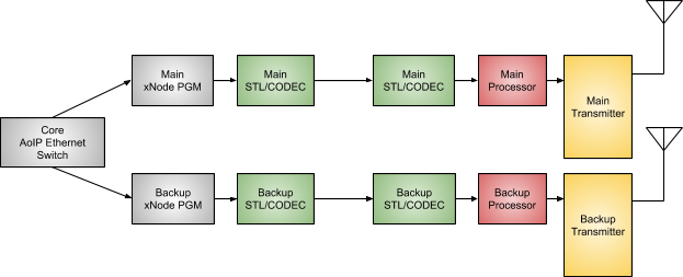
Imagine a radio station with both main and backup transmitting antennas, fed by separate transmission lines, connected to main and backup transmitters, which are fed from the studio by main and backup STL systems. In an AoIP environment, the engineer would be smart to feed these two STL systems with separate outputs from different xNodes on the Livewire+ network. This arrangement brings the redundancy of the STL and transmission chain right into the Livewire+ system. It means that a failure of the output on an AoIP node doesn’t have to affect on-air operations, as a redundant xNode is still feeding the main or backup air chain.
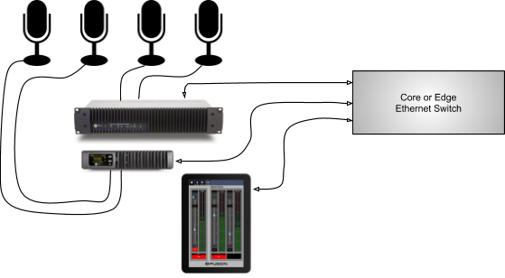
Other redundancies may be designed-in to AoIP systems as well. For example, if a given studio has 4 talent mics and is equipped with a QOR.16 Integrated Mix Engine, a Telos Alliance Mic xNode can bring in 2 of the mics while the QOR.16 is bringing in the other 2 mics. A failure of either the QOR.16 or the Mic xNode still leaves 2 mics connected to the Livewire+ network. Indeed, using Axia’s IP-Tablet software, the Mix xNode can act as a temporary mixing console with 4 inputs—enough to handle a basic show or some voice-tracking.
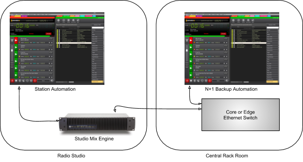
When thinking about redundancy, we might consider connecting a backup (or N+1) automation playout system in such a way that its associated studio could go offline, but the backup automation system would still be on the Livewire+ network and able to keep programming going. This approach demonstrates the value of connecting backup systems to different points on the AoIP network than the systems they’re backing up. That way a failure or disconnect of one system doesn’t affect its backup.
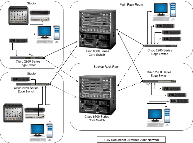
Though a multicast AoIP network may have more than one Ethernet switch, what it may not have is more than one switch acting as the “IGMP querier.” Why? Because the IGMP querier is the switch that is in charge of managing and maintaining all of the Livewire multicast streams on the network. This means that all AolP multicast packets must travel through one Ethernet switch. On a network diagram it looks as though this one Ethernet switch represents a single point of failure. On first glance this is true. Failure of the core switch, providing IGMP querier services, as well as switching of packets among local equipment and other “edge” switches, will stop all such connectivity. And, while it’s true that only one Ethernet switch at a time may handle this key function, there are several approaches to providing redundancy to the IGMP querier function. Let’s consider four networking options that offer us complete redundancy in the core Ethernet switch.
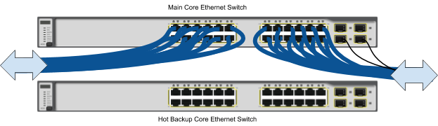
First is a completely manual solution. When we install our Livewire+ network, we simply purchase and identically configure two core Ethernet switches. The two are rack-mounted right next to each other, but only one of them will be connected and actively used. The other sits as a hot standby. Should the in-use core switch fail, the Ethernet cables from the failed switch are simply moved to similar ports on the standby core switch. Within a few seconds to a couple of minutes, all the tables and IGMP groups are rebuilt automatically by the replacement switch, and the system is up and running. Although this is a manual cutover to a hot standby switch, the cost and complexity of this approach are quite low.
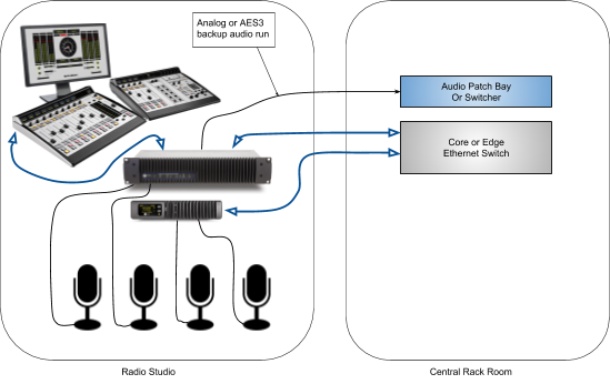
Note that during such a failure—and absence—of the core Ethernet switch, the various studios and other AoIP equipment clusters will continue to work with other equipment that’s connected to the same edge switch. For example, if an AoIP-connected automation playout system is connected to the same edge switch as its studio’s audio console, those devices will revert to sharing audio streams as their local edge switch can become the IGMP querier for those devices. As such, they will continue to operate. A smart backup tactic is to wire an analog or AES3 output from each isolated studio back to the central rack area, thus providing an emergency feed of Program Audio from each studio. This backup, non-AoIP feed can be wired to an audio processor’s failover input, or to a simple patching system.
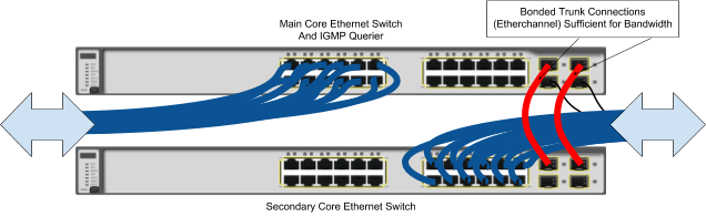
A variation on the manual core switch cutover approach is to size the switches such that either one can take all the necessary connections, but then actually use the hot standby core switch for about half of the Livewire+ Ethernet connections. In this method devices and other switches from around the facility are connected to either one or the other of these switches. Each switch has its own IP address, but the one with the lower IP address asserts itself as the IGMP querier through an election process. If the IGMP querier switch fails, then the other switch (configured with its IP address as just one higher) will take over that function. If the non-querier switch fails, then the querier function is unaffected. Naturally, all devices plugged into the failed switch will stop communicating until they’re moved over to the good switch. The good news is that all devices on the good switch will continue to operate normally. Note that if the IGMP querier function has to move from one switch to another, there will be some brief outage while the IGMP querier function gets established in the non-failed switch. For this method to work, it will also be necessary to establish one or more bonded trunk ports between the two switches, as all packets—even those connecting through the non-querier switch—still need to route through the querier switch. In other words, all of the packets still must travel through the active IGMP querier, and we must give them a high-bandwidth connection (in aggregate) from the non-querier switch to the querier switch.
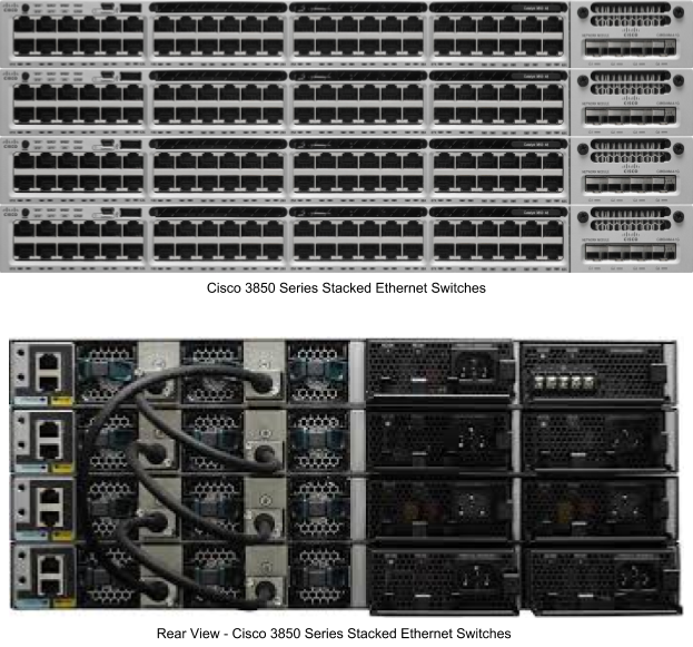
Another approach to core switch redundancy is to use “switch stacking.” This method is similar to the previous method, except that a stackable switch is set up to operate together with one or more other network switches, with this group of switches showing the characteristics of a single switch but having the port capacity of the sum of the combined switches. Switch stacking can provide backup power supply capability and convenient management of multiple switches. Commonly used switch models are the Cisco 3650 and 3850 series of Ethernet switches.
Some of the most robust redundant core switch implementations are affected using Cisco 4500 or 6500 series switches. These are available in models designed specifically when redundancy is critical. Ordered with appropriate options, they have dual power supplies and dual Supervisor Blades. Plus their architecture is a blade construction such that smaller groups of ports are replaceable with a quick swap of a module. Some of the largest and most mission-critical Livewire+ networks are using these large Cisco Ethernet switches, due to the options they provide for extremely high availability via their multiple layers of redundant systems.
One final approach, taken by several of the largest Livewire+ networks, employ high-end Cisco Ethernet switches along with an alternative to the IGMP querier. This method uses PIM and mrouter to route multicast traffic in a complex or distributed network environment.
Protocol-Independent Multicast (PIM) is a family of multicast routing protocols for Internet Protocol (IP) networks that provide one-to-many and many-to-many distribution of data over a LAN, WAN, or the Internet.
An mrouter, or multicast router, is a router program that distinguishes between multicast and unicast packets and determines how they should be distributed along the Multicast Internet (sometimes known as the Multicast Backbone or MBone).
The complexities, and required local expertise, of using PIM and mrouter approaches results in a key benefit: little or no delay in re-establishing multicast routes after an Ethernet switch interruption.
Using PIM and mrouter, rather than the far more common IGMP querier, is an option for large, diverse, or perhaps highly critical AoIP networks. Facilities wishing to explore the particular benefits and implementations of this last approach will want to consult with Cisco-certified experts who would be responsible for network design, configuration, and maintenance.
Any AoIP networking can be simple, but the details do matter. Whether your proposed Livewire+ network is simple and straightforward, or is quite large, or has special considerations—the Telos Alliance Support Team is standing by to assist. Your AolP network will be transporting and routing every millisecond of audio and metadata that your studios produce or broadcast. Let’s make sure the network foundation is solid, and the network configuration details are where they need to be.
Telos Alliance Support:
E-mail: support@telosalliance.com
Phone: +1 (216) 622-0247
Further Reading
Make a Proper IP Address Scheme for Your Livewire Facility
Telos Alliance has led the audio industry’s innovation in Broadcast Audio, Digital Mixing & Mastering, Audio Processors & Compression, Broadcast Mixing Consoles, Audio Interfaces, AoIP & VoIP for over three decades. The Telos Alliance family of products include Telos® Systems, Omnia® Audio, Axia® Audio, Linear Acoustic®, 25-Seven® Systems, Minnetonka™ Audio and Jünger Audio. Covering all ranges of Audio Applications for Radio & Television from Telos Infinity IP Intercom Systems, Jünger Audio AIXpressor Audio Processor, Omnia 11 Radio Processors, Axia Networked Quasar Broadcast Mixing Consoles and Linear Acoustic AMS Audio Quality Loudness Monitoring and 25-Seven TVC-15 Watermark Analyzer & Monitor. Telos Alliance offers audio solutions for any and every Radio, Television, Live Events, Podcast & Live Streaming Studio With Telos Alliance “Broadcast Without Limits.”
More Topics: Livewire